
August 2025 Update:
Due to the originally-listed app being removed from the App Store, this guide was refreshed with updated app options, new code, and a small wiring fix. Please see sections 5 and 6 for details of the updates.
1. General Introduction
Have you ever wanted to build your own HUGE? Now you can! Thanks to our sponsor Mouser Electronics, we’ve put together a kit and guide to make your own replica HUGE. We’ve constructed this project to be:
Less than $100 (roughly)
Simple and beginner-friendly
Requires no soldering, and no advanced tools to create
Controllable from a Bluetooth phone app
Free on Android, Paid on Apple iOS
Arms you, the robot builder, with the pieces and parts you need to embark on future robotics projects!
For compatibility’s sake, this project was designed and tested on a Windows 10 PC, with app control through a Bluetooth app on a Samsung Galaxy S10e phone running Android 12. We have not tested these steps with other operating systems and devices, so proceed at your own risk.
This project will be published in the following stages:
General Introduction
Materials Lists
Chassis Construction
3D Printed Version
Cardboard Version
Electronics Introduction
Wiring
Code & Bench Testing (ready, but troubleshooting a coding bug. Code provided with caveats)
Final Integration
Fun! (hasn’t that already started?)
This is what you’re building towards:

2. Materials Needed
Below you’ll find our parts & materials list needed to complete the project. You can choose to use a 3D printer to complete the construction of the chassis (robot body) OR good old fashioned cardboard and hot glue. We’ve broken the materials down by supplier for ease in purchasing – that being said, if you already own super glue, pliers, etc. feel free to use your own!
From Mouser Electronics
9v Battery Snap
Part Number = 123-5025-GR
Quantity Needed = 2
Cost = $1.98
TT Motor Mount
Part Number = 485-3768
Quantity Needed = 4
Cost = $6.00
TT Motor Snap-On Hub
Part Number = 485-3769
Quantity Needed = 4
Cost = $7.80
Sparkfun TT Motors (Pair)
Part Number = 474-ROB-13302
Quantity Needed = 2 pairs needed
Cost = $15.14
Main Control Board & Drive Motor Controller
Part Number = 426-DFR0351
Quantity Needed = 1
Cost = $25.90
Weapon Motor Controller
Part Number = 426-DRI0002
Quantity Needed = 1
Cost = $12.90
9v Batteries
(Available at any store)
Quantity Needed = 2
Cost = Around $9
Female/Female Jumper Set
Part Number = 485-1950
Quantity Needed = 1
Cost = $1.95
Female/Male Jumper Set
Part Number = 485-1954
Quantity Needed = 1
Cost = $1.95
Micro USB Cable
Part Number = 166-USBCABLEMICRO80
Quantity Needed = 1
Cost = $2.48
Total Estimated Cost = $85.10
From Bolt Depot
Or, feel free to visit your local hardware store.
M4 Nut
Part Number = 4784
Quantity Needed = 12
Cost = $0.60
M4 x 16mm Bolt
Part Number = 17887
Quantity Needed = 2
Cost = $0.16
M4 x 10mm Bolt
Part Number = 17884
Quantity Needed = 10
Cost = $0.70
Total Estimated Cost = $1.46
From Lowe’s
Or your local hardware store.
Command Strips (If you don’t already have some)
Part Number = 17024-48ES
Quantity Needed = 1
Cost = $11.88
Kobalt Screwdriver (Tiny screwdriver - if you don’t already have one)
Part Number = KBSWT29
Quantity Needed = 1
Cost = $8.98
Pliers (If you don’t already have them)
Part Number = 59343
Quantity Needed = 1
Cost = $5.98
Tiny Zip Ties (If you don’t already have them)
Part Number = SGY-CT3
Quantity Needed = 1
Cost = $5.48
Total Estimated Cost = $32.32
————
[If using a 3D Printer]
————
From PolyMaker
Or wherever you like buying your 3D filament (ensure you buy the correct filament thickness
(If using a 3D printer) White 2.85mm PLA
Part Number = PA02017
Quantity Needed = 1
Cost = $22.99
(If using a 3D printer) Blue 2.85mm PLA
Part Number = PA02020
Quantity Needed = 1
Cost = $22.99
Purple glue stick - necessary for a 3D printer, but brand and variety are up to you!
————
[If NOT using a 3D Printer]
————
We didn’t provide purchasing recommendations for these parts, we hope you don’t mind. Any brand will do!
Some Cardboard, ours was a little less than 1/8” thick
Some Paper
X-Acto or other craft Knife
Glue stick (regular)
Small hole punch (note - in the video we used a screwdriver because we didn’t have one, but really anything you can use to punch a hole in some cardboard will work!)
Hot glue & hot glue gun
Regular printer (to print our cutout guides)
Scissors
Total cost of project (roughly) = $120
*Total actual cost depends on how many tools you already own, shipping, sales, tax, etc. Suggested Apple iOS app is also paid ($3.99).
3. Chassis Construction
What is a Chassis? How is it pronounced? Why the heck are we calling it that? Well – a “Chassis” is a term used in construction and engineering that basically means the structural frame. When we talk about it in terms of HUGE, we mean the body of the robot. It just sounds fancier that way.
Now that we’ve learned a new word, let’s get down to construction.
(Note: If you’re not using a 3D printer, scroll down to the cardboard construction directions)
3d Printed Instructions
3D print the following files from your favorite filament. We used PLA.
Wheel.stl - Quantity 2
Kit Eye.stl - Quantity 2
Support Leg.stl - Quantity 2
Spinning Blade.stl - Quantity 1
Spinning Blade Spacer.stl - Quantity 3
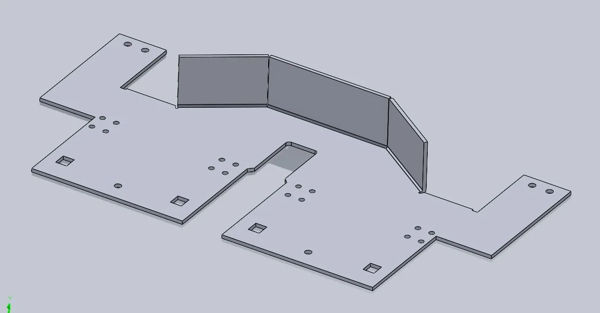
If you have a printer with a 6” x 6” size limitation, files were included to split the main body into two pieces. If you have this limitation, print the following:
Frame For Printing - Left Half.stl - Quantity 1
Frame For Printing - Right Half.stl - Quantity 1
Top Plate - Left Half.stl - Quantity 1
Top Plate - Right Half.stl - Quantity 1
If your printer does not have a size limitation, you can print the following files. NOTE: We have not tested these files, as our printer is too small. We anticipate that there could be issues with removing the supports from the “Frame for Printing” file.
Frame For Printing - Full.stl - Quantity 1
Top Plate - Full.stl - Quantity 1
If you printed the split frame pieces, then you must glue the base frame together. For this, we use liquid super glue to attach the frames at the rear, behind the blade. Don’t worry about gluing the top plate halves together.

Apply glue to the highlighted portion.
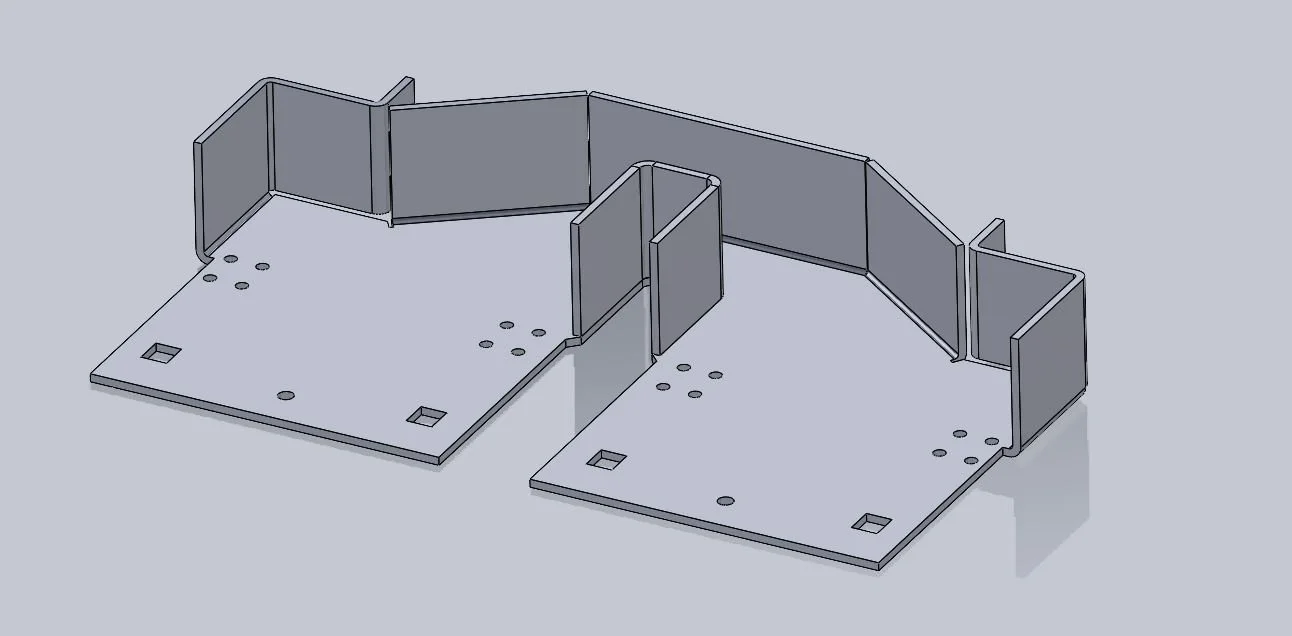
After removing the 3d printing supports, we added some tape to the bottom of the chassis, with it perfectly aligned. After adding the tape, we stood the chassis up on-end to add glue to the edges. Once glued, we added tape elsewhere to secure the chassis in place, and waited for the glue to dry. Once dry, remove the tape. You did it! You now have a chassis. Move onto the electronics portion of the guide.
Cardboard Instructions
Printing Notes
You’re going to want to print the wheel page out twice
Find and select an option for “Print Actual Size”. Your printer may shrink these files before printing, and they must match the original sizing for components to fit.
If the printer does not print any of the chassis corners, simple redraw it with a pen and a ruler.
Cut the files out roughly. Once it’s on the cardboard, you’re going to want to cut more precisely.
Glue the paper onto your cardboard, using a glue stick.
Note - we have an overlapping section on the main body (because we wanted to use a normal 8.5x11 printer) there is a marking on the sheet on where to overlap. We strongly recommend watching the video to illustrate this better.
Poke holes. It’s much easier to poke the holes out at this point. We recommend either a small hole punch or anything you can use to poke holes in cardboard. In our video we used a screwdriver of appropriate size.
Cut out the shapes from the cardboard using scissors, a craft knife, and a hole punch. You’ll want to cut along the solid outer black outline. At this point you’ll have a irregular-looking shape for the main body, and many flat finished pieces.
To form the chassis of the robot, the base body will be folded together, and hot glued into place. Folds will be done along the dotted lines, and hot glue should be used along joints between bends. There is also a video of the full process at the bottom, and a gallery showing the steps below.


We recommend starting with the back. Fold up the back outer squares along the dotted lines.
Fold the neighboring diagonal panels along the dotted lines. Glue these to the rear outer squares.
Fold up the side panels - which have additional folds on them to form the remainder of the back panel and the leg mounts along the dotted lines. Glue these to the floor, and glue the rear panels to nearby diagonal panels.
Fold the rectangular piece from the “Miscellaneous Flat Parts” along the dotted lines. This forms an internal guard to keep wiring out of the weapon blade. Glue this onto the rear of the weapon channel.
Fold the front faces upwards along the dotted lines.
Glue the brim to the fronts using hot glue
Flex the brim down and hot glue it to the entire rest of the chassis (it will take a lot of hot glue)
You did it! You now have a chassis. Move onto the electronics portion of the guide.

The camera battery died, just before the cardboard chassis was completed. Here is a photo of the completed chassis.
4. Electronics Introduction
Electronics! Without them, our robots are little more than paperweights. These electronic components have a lot of responsibility, and do multiple jobs simultaneously. First, they handle the wireless connection between the robot and controller. They also take charged power stored within the batteries, and divert it to power the motors and the boards themselves.
Our circuit uses two control boards, one each for the drive and the weapon. In addition, the drive control board handles the wireless connection, and stores the programming code that instructs the whole system on how to operate! Each control board uses its own 9V battery, and a few wires are run between the boards so that the drive control board can instruct the weapon control board on what to do.

A size comparison between the batteries of the Build-Your-Own HUGE (front) and the competitive 250lb HUGE from BattleBots (rear).
5. Wiring
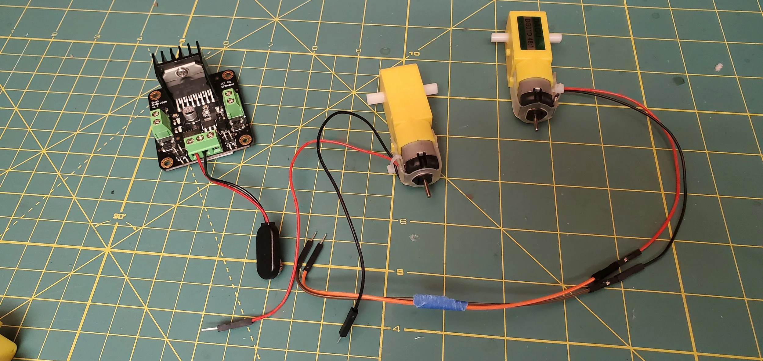
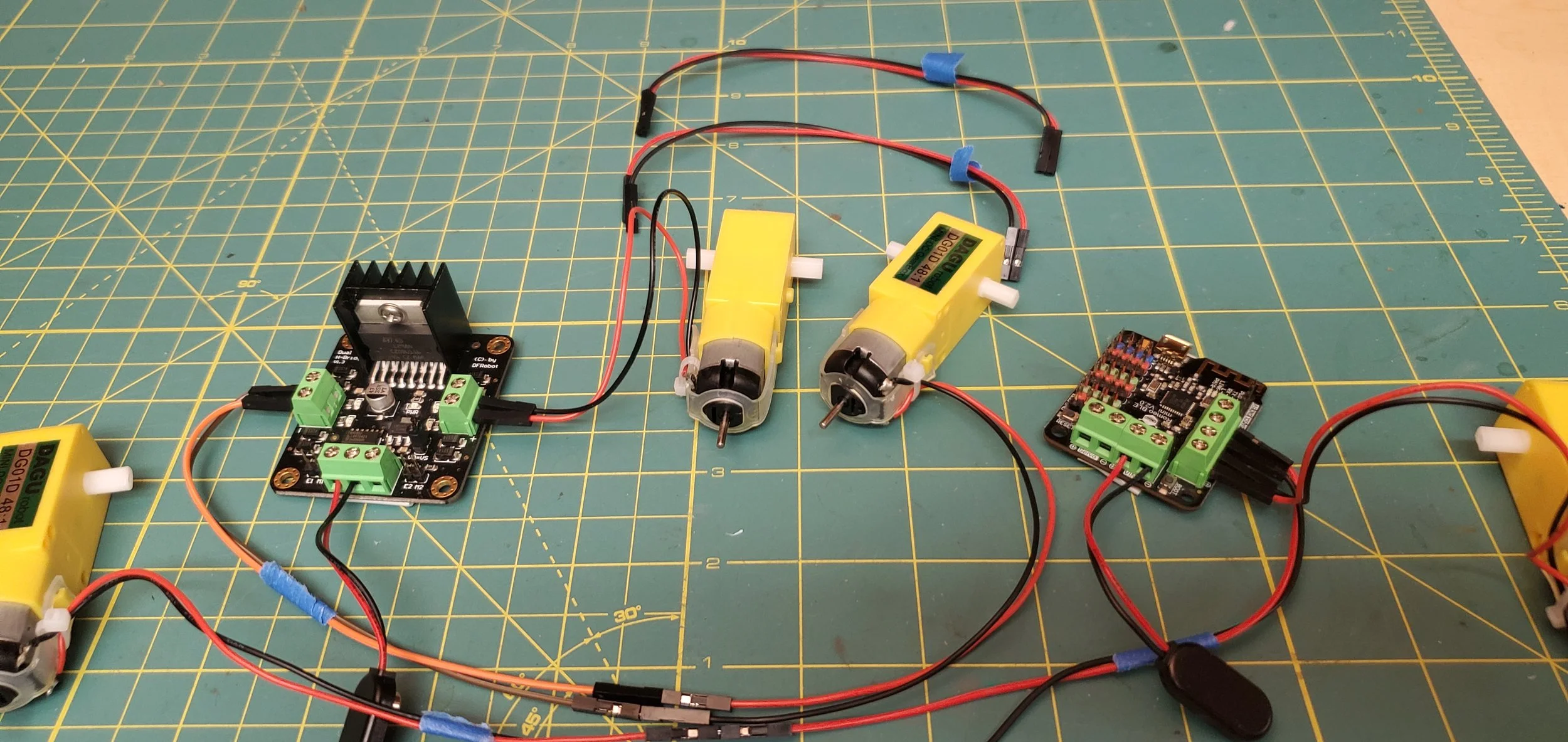
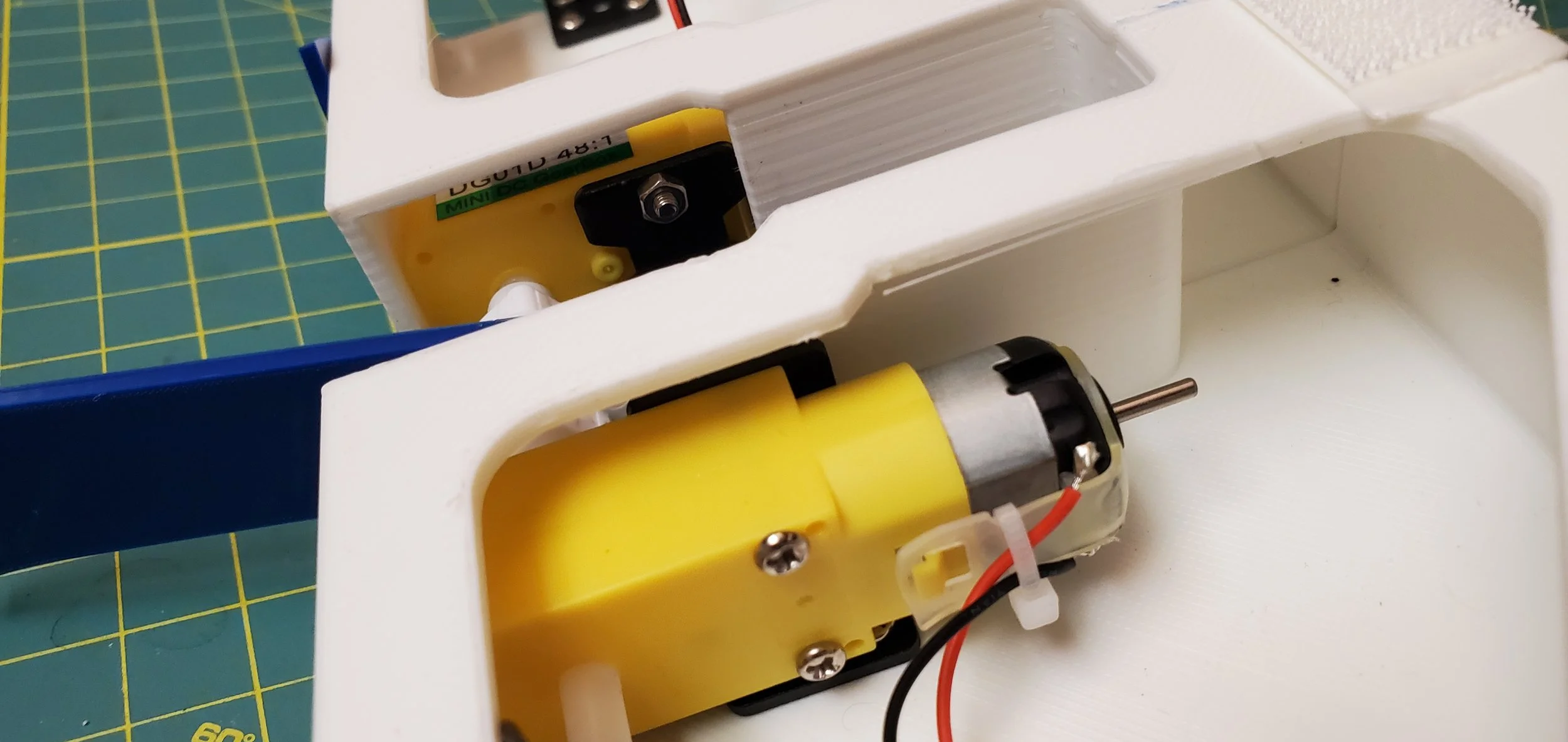
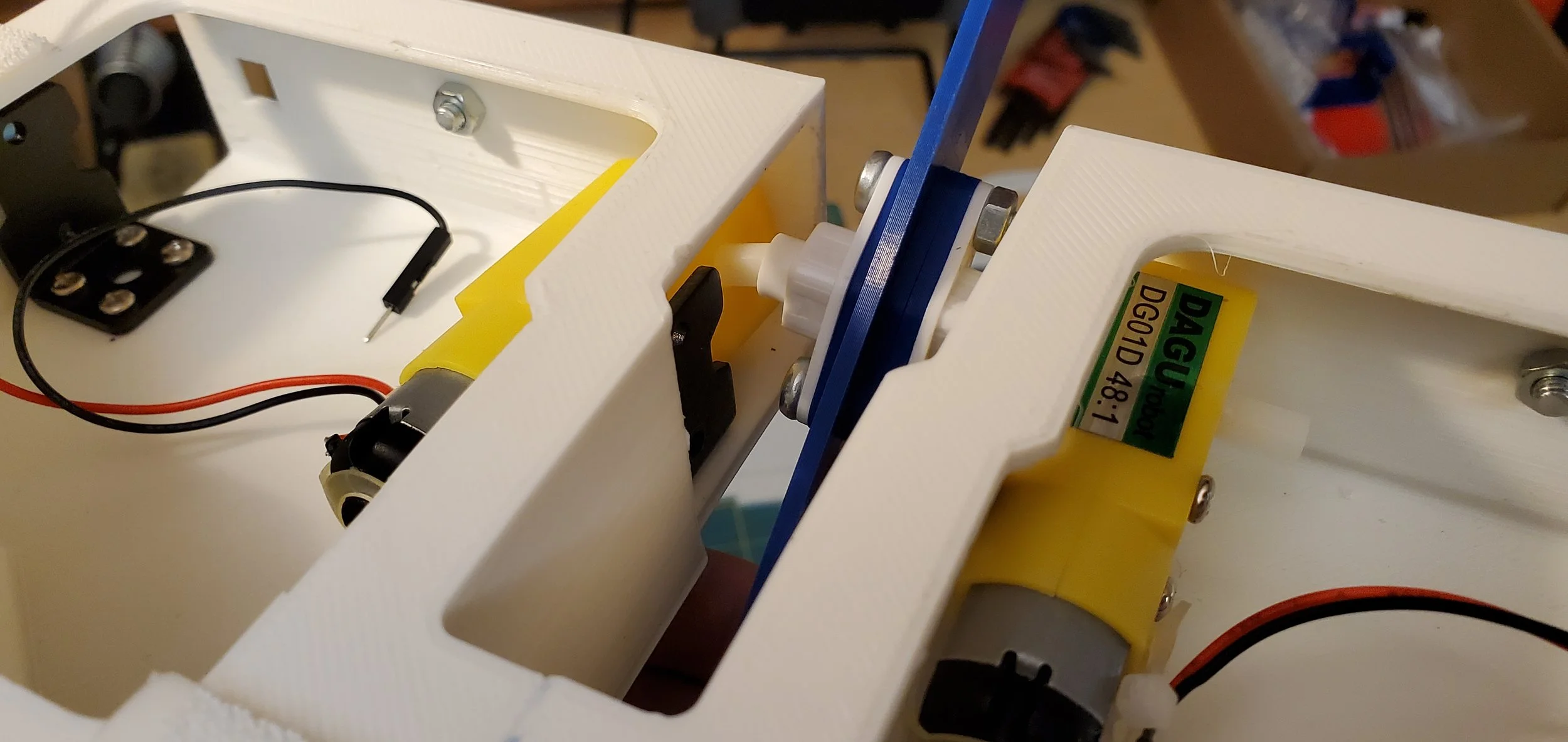
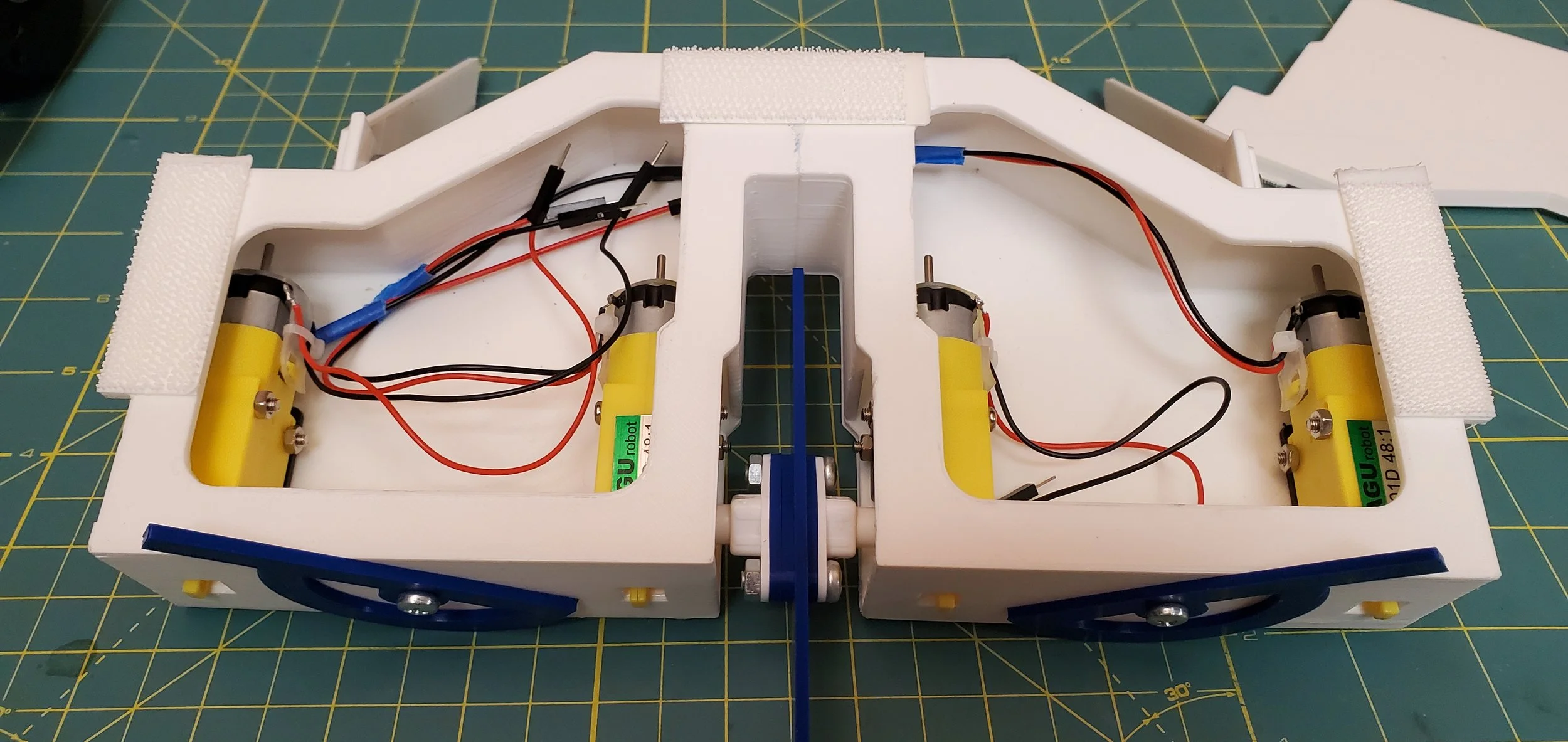
Before installing them in the robot, assembling the electronics separately (“bench testing”) can help to troubleshoot issues, allow you to easily install the code, and ensure that all motors are turning in the correct directions. To begin with, lay the electronics on the table in the layout that they eventually will use inside the robot:
Two motors in the center, with wiring facing away from the center, for the weapon
Two motors at the edges, with wiring facing towards the center, for the drive wheels
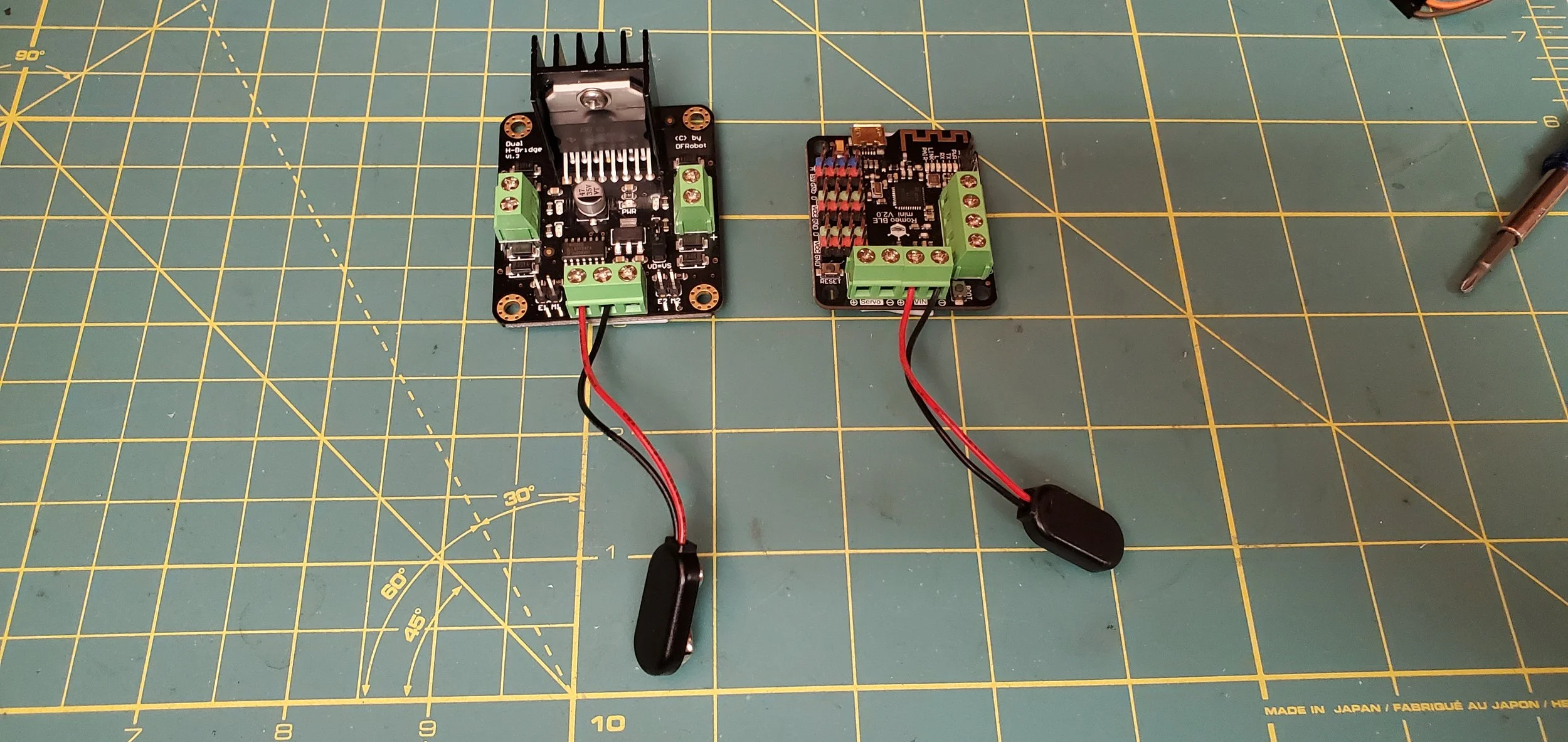
Weapon Motor Controller on the left side of the robot, with the large black heat-sink facing the front of the robot
Main Control Board/Drive Motor Controller on the right side of the robot, with the small USB port facing the front of the robot
One 9v Battery Snap behind each motor controller, lined up with (but not connected to) one 9V Battery per side.

An example of the robot’s wiring, installed within the chassis. Do your best to imitate this layout.
First, we are going to install the 9v battery snap connectors into the motor controllers.
On the drive motor controller, look for the rows of screw terminals at the back. A pair of them will be marked “VIN”, with a + and a -. To decode the engineering shorthand, VIN = V IN = Voltage In = Electricity input into the motor controller. This is where we will connect the battery snap. Screw the red wire into the + terminal, and the black wire into the - terminal. Note: Do not plug in the battery yet.
On the weapon motor controller, look for the row of screw terminals at the back. Connect the red wire of the second 9v battery snap connector to the “VD” terminal, and the black wire to the “GND” terminal. In addition, check for the “VD=VS” jumper to be connecting two pins in the center of the weapon motor controller board. The board is designed to separate motor power input (VS) from control board power input (VD). We don’t need these separated, and it simplifies wiring to have this jumper installed. It should be included with the board, but if it is not, replacements can be purchased here. The jumper is shown photographed below, in the photo with the screwdriver pointing towards it.


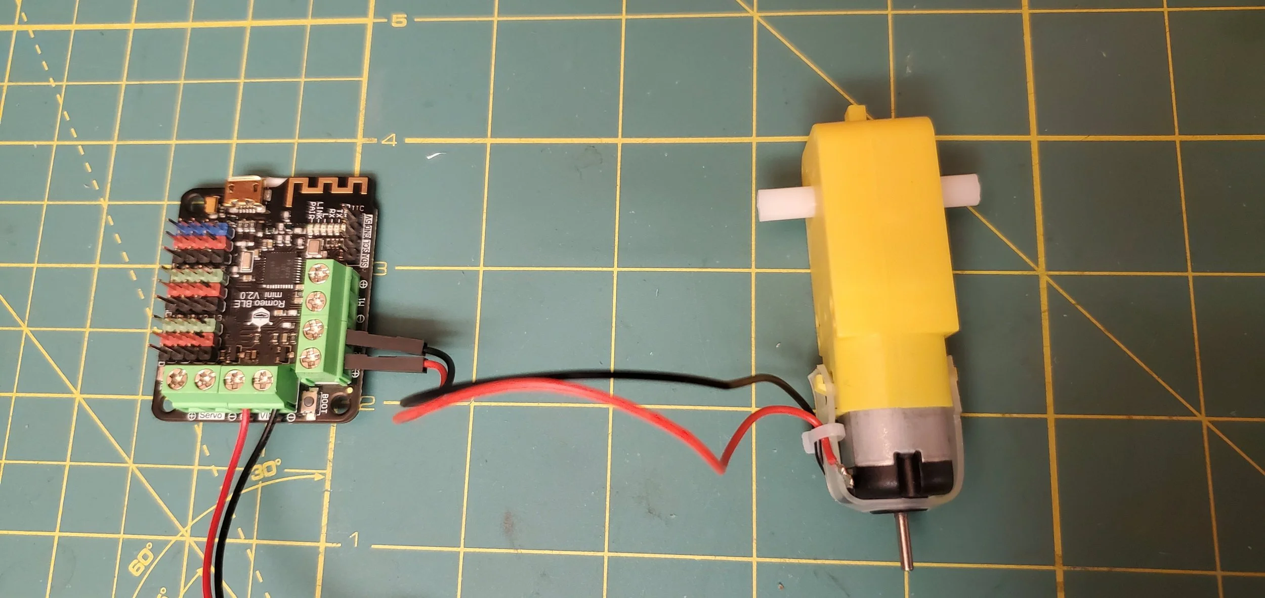
Now that the controllers have power wiring, let’s worry about the drive motors next. A quick note: following these instructions carefully is very important. Without correct motor wiring, the robot will not drive properly! For the drive motor on the right side of the robot, next to the drive motor controller, wiring is simple. First find the screw terminals labeled “M2” (meaning Motor 2). Connect the red wire to the + terminal, and the black wire to the - terminal. For the motor on the left side of the robot, its wires are far too short to reach. Use your Female/Male wire extensions to reach the drive motor controller. Insert the red wire into the + terminal, and the black wire into the - terminal.


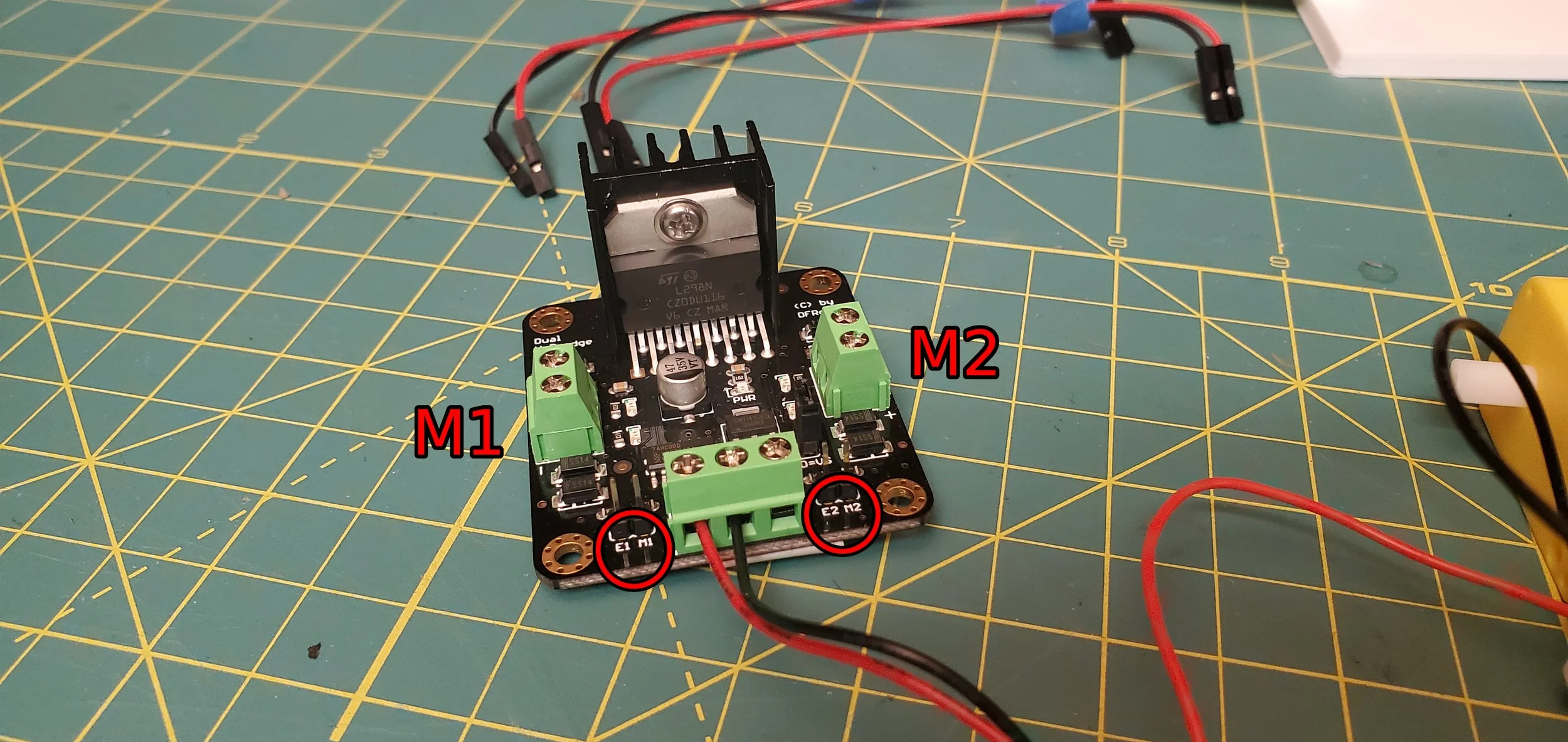
The weapon motors come next, and these will be routed to the weapon motor controller on the left side of the robot. Make sure you find the two remaining sets of screw terminals on the weapon motor controller, one set on each side. Each side also has a pair of male header pins, marked “E1, M1” on the left side of the controller, and “E2, M2” on the right side of the controller. We’ll be connecting wires to these later, but for now they are relevant for teaching us which set of screw terminals is “Motor 1”, and which set is “Motor 2”.
For the weapon motor on the left side of the chassis (immediately next to the weapon motor controller), we’ll be using the screw terminals for Motor 2. Connect the red wire to the + terminal, and the black wire to the - terminal. For the weapon motor on the right side of the chassis, you’ll once again need your Female/Male wire extensions. For this motor, we’ll be using the screw terminals for Motor 1. Connect the red wire to the - terminal, and the black wire to the + terminal.
“Hey!” you might shout, “that is backwards from before!”. You are correct, but there is a reason! The weapon motors must technically spin opposite directions, due to their layout within the robot and the specifics of how the motor controller functions. We can accomplish this easily and safely by reversing the power wires of the motor as they screw into the board. If any motor is spinning opposite of its expected direction, reversing the power leads should be the first thing you try for troubleshooting!


The final wiring step is to connect the motor controllers together, so that the brains (the drive motor controller) can tell the weapon motor controller what to do. To accomplish this, you will need your Female/Female Wire Extensions. Begin by finding the E1, M1 and E2, M2 header pins again, on the weapon motor controller. Attach red wire extensions to E1 and E2, and black wire extensions to M1 and M2. Set these aside for now. On the drive motor controller, look for the field of header pins, and specifically look for the pins with green plastic bases and numbers printed next to them. In comparison to the red and black header pins, we can control the output of the green pins! (And also the blue pins, but we won’t be using those). Each of the Female/Female Wire Extensions from E1, M1, E2, and M2 will find homes within these green pins. Make the following connections:
E1 (red) to pin 11
M1 (black) to pin 13
E2 (red) to pin 3
M2 (black) to pin 9

And that’s it! You have wired your robot on the bench! From here, we move on to coding.
August 2025 Update:
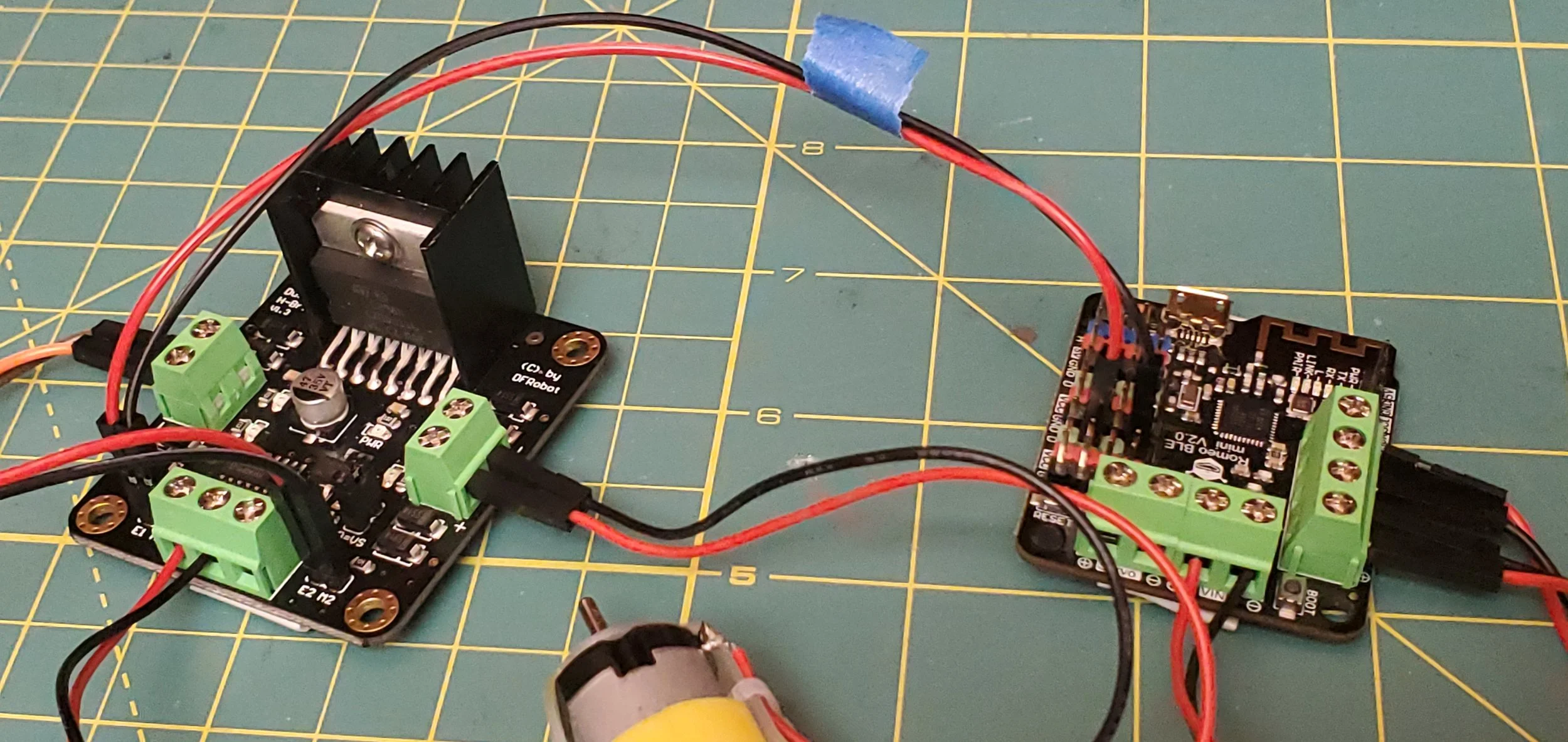
A single extra wire should be added to connect the two control boards together. This wire’s purpose is to unify the Negative side of each of the separate 9V batteries. When the batteries are operating at different voltages (AKA, one is drained further than the other), the voltage levels of the boards can fall out of sync with each other. This may cause the weapon motors to not activate when the button is pressed.
Once again, you will need a Female/Male Wire Extension for this. With the female end first, connect it to one of the “GND” male headers pins on the Main Control Board. Then the male end is run over to the Weapon Motor Controller. Gently unscrew the “GND” screw terminal, where the battery plugs in, and insert this extra jumper alongside the battery leads. A photo of this extra wiring is shown in detail below.

The newly-added jumper cable is the purple wire, at the front of the photo crossing between the boards. Connect the female end to a “GND” header on the main board, and the male end into the “GND” screw terminal (alongside the battery connector) on the weapon control board.
6. Coding & Bench Testing
“Coding”, a word that strikes fear into the heart of many mechanical engineers. Code doesn’t have to be that scary though! Arduino-based platforms, like the one used in this project, can be the basis for many different projects and electronics systems. While these instructions won’t teach you how to code for Arduino, it will be a great excuse to purchase everything you need and set you up for future projects!
To begin, download the Arduino software for interfacing with the Drive Motor Controller. At the time of writing, this was Arduino version 1.8.19 and it was used for all subsequent testing (including the 2025 update).
https://www.arduino.cc/en/software
Then find the Micro USB Cable purchased earlier, and connect the Drive Motor Controller to a USB port on your computer. You will see a small light turn on on the drive motor controller, indicating that it has power. Try not to touch the board itself while it is powered on, or you may damage it! Our first steps will be to configure the Arduino software to interface with the board. Underneath the “Tools” dropdown, find the “Board” dropdown and select “Arduino Uno”. Then, also under the “Tools” dropdown, open the “Port” dropdown and select the board from the available connections. In our case, the board was the only available connection, and was connected via “COM4”. Yours may have a number other than 4, but likely will still have “COM” in the title.

Ensure that your arduino configuration matches this.
Next, open the code file (known as a “sketch”) from within the Arduino app. This is literally the brains of the operation! This code was developed with the help of ChatGPT, but feel free still to read the manufacturer documentation for more technical details on how to work with this board. For total beginners, AI tools can certainly help.
This is a simple program, and functions by submitting a letter via the serial monitor. Depending on the character submitted, a number of functions can take place. The weapon can be turned on or off, and the robot can drive forwards, backwards, and turn left and right (for a set duration of time). To ensure the code is written properly, click the check-mark in the top left corner of the Arduino tool to “Verify” the code. This will tell you if there are any bugs, and compile the code for you. After seeing “Done Compiling” appear in the bottom left corner, click the arrow that reads “Upload”. Once “Done Uploading” appears in the bottom left corner, you are ready to run!
To allow the motors to actually turn, we now plug in one of our 9V batteries for the first time, to the drive motor controller. It is extremely important that you plug the battery in with the correct direction of the terminals! Doing this step backwards can damage the control boards. The polarity is shown in the photo below: plugs of opposite sizes interface together. If you would like to be extra safe, you can remove the 9V battery snap from the board (unplug it from the computer first) and connect it to the 9V battery elsewhere. Then reinstall into the motor controller. If it doesn’t snap together and hold, then the polarity isn’t correct.

Make sure your 9V battery is connected properly, or you risk damaging your controllers!
First, we are going to test the electronics via the serial monitor. With the board still plugged into the computer (but also with the 9V battery plugged in), open the serial monitor using the Magnifying Glass styled button in the top right corner of the Arduino software. First, we double-check a couple of settings in the bottom-right corner of the window:
Ensure that the “baud rate” is set to 115200, to match the code and the board’s defaults
Ensure that the “line ending” is set to “No line ending”, so the software doesn’t append anything to what you submit
It’s time to test! Type any of the following commands, and press the “Enter” key to submit them.
“F” will turns drive motors forwards for a short pulse
“B” will turns drive motors backwards for a short pulse
“L” will turns opposing directions for a short pulse
“R” will turns opposing directions for a short pulse
If that works, excellent! Now connect your second 9V battery to the weapon motor controller. Another light should come on there, once it is connected. Now try the following commands.
“S” will begin the weapon motors spinning continuously
“X” will stop the weapon motors from spinning
If this all works, congratulations! Submitting anything other than these 6 letters will yield no response, and these 6 letters will form the basis of the buttons that we’re going to create next, for controlling the robot. Now let’s get it working wirelessly. This will include instructions for both Apple and Android devices. This was tested with an Apple iPhone 16 on iOS 18.6, and a Samsung Galaxy S10e on Android 12.
Apple: BLE Serial Pro ($3.99)
Android: nRF Connect (Free)
After downloading the relevant app, first look under your cell phone’s normal bluetooth connections window, look for “Bluno”, and select it. If it is named something else, you should be able to rename it to whatever you like within these settings. When prompted for a password, enter “000000”. This will pair the arduino with your phone. Exit out of this window and open the app now.
Android App Setup (nRF Connect):
Once in the app, tap the “SCAN” button in the top right corner. Once it appears in the list, tap the “Connect” button on the “Bluno” tile to connect with it.
If this connects, you should see a blue light appear on your drive motor controller. If it does, that’s a great sign! If not, double-check wiring, app setup, etc. If nothing seems wrong, feel free to reach out to us and we can take a look (contact info at bottom of page).
Once connected, we move on to how to control the robot. This will make use of the “Macros” functionality in this app: Tap the RED circle in the bottom right corner of the screen.
Once the Macro window is open, tap the button to Import Macros, which is shown below.

nRF Connect Setup
ANDROID MACROS CAN BE DOWNLOADED HERE
Click the “Import” button after downloading to pull the functions into nRF Connect. Once there, tap each icon to control the robot.
After unzipping the folder on your phone, import all six macros. Each should send a different letter pulse to board, causing the robot to move!
Tap buttons quickly to run the drive motors, and turn the weapon motors on and off!
Apple App Setup (BLE Serial Pro):
Before connecting to the board, open the app settings in the top left corner. The config settings need to be changed so that you can connect to the board.
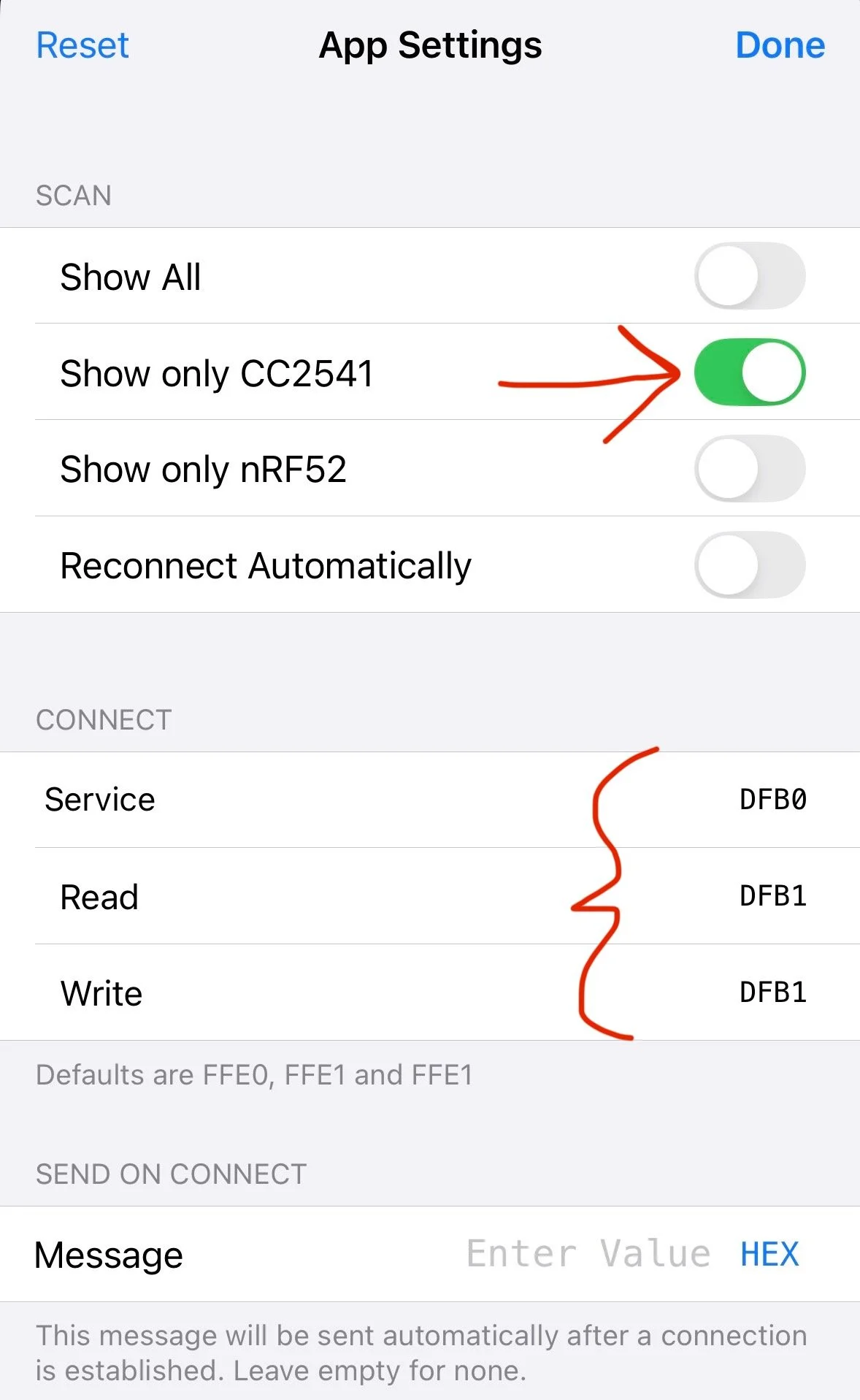
BLE Serial Pro Setup
First, check the box for “Show only CC2541”. Then, update the “Service”, “Read”, and “Write” boxes to match the photo.
Service -> DFB0
Read -> DFB1
Write -> DFB1
Without these changes, the app will not connect to the board.
Once done, go back to the main app page and power on the control board. Refresh the page until “Bluno” appears, then tap to connect with it.
If this works, you should see a blue light appear on your drive motor controller. If it does, that’s a great sign! If not, double-check wiring, app setup, etc. If nothing seems wrong, feel free to reach out to us and we can take a look (contact info at bottom of page).
From here, we can get the robot working. After connecting, click into the “Functions” tab, and click on the crossed pencil and ruler icon at the top (which lets you create functions).
You will need to program one separate button each for “Forwards”, “Backwards”, “Left”, “Right”, “Spinner On”, and “Spinner Off”.
Each button should be created with the following settings:
Name and color
Message format should be “UTF8”
(select this from a dropdown list when tapping that area of the screen)
Repeated sending on, and set to 5khz
(This enables continuous motor control, instead of having to repeatedly tap the buttons to drive)
Set “Message” to the letter that the onboard program is looking or. These are as follows:
F -> “Forwards” -> Robot drives forwards
B -> “Backwards” -> Robot drives backwards
L -> “Left” -> Robot turns left
R -> “Right” -> Robot turns right
S -> “Spinner” -> Spinner turns on
X -> “Spinner Off” -> Spinner turns off
Hold buttons to run the drive motors, and tap the relevant buttons to turn the weapon motors on and off! The weapon button is programmed so that it doesn’t need to be held.
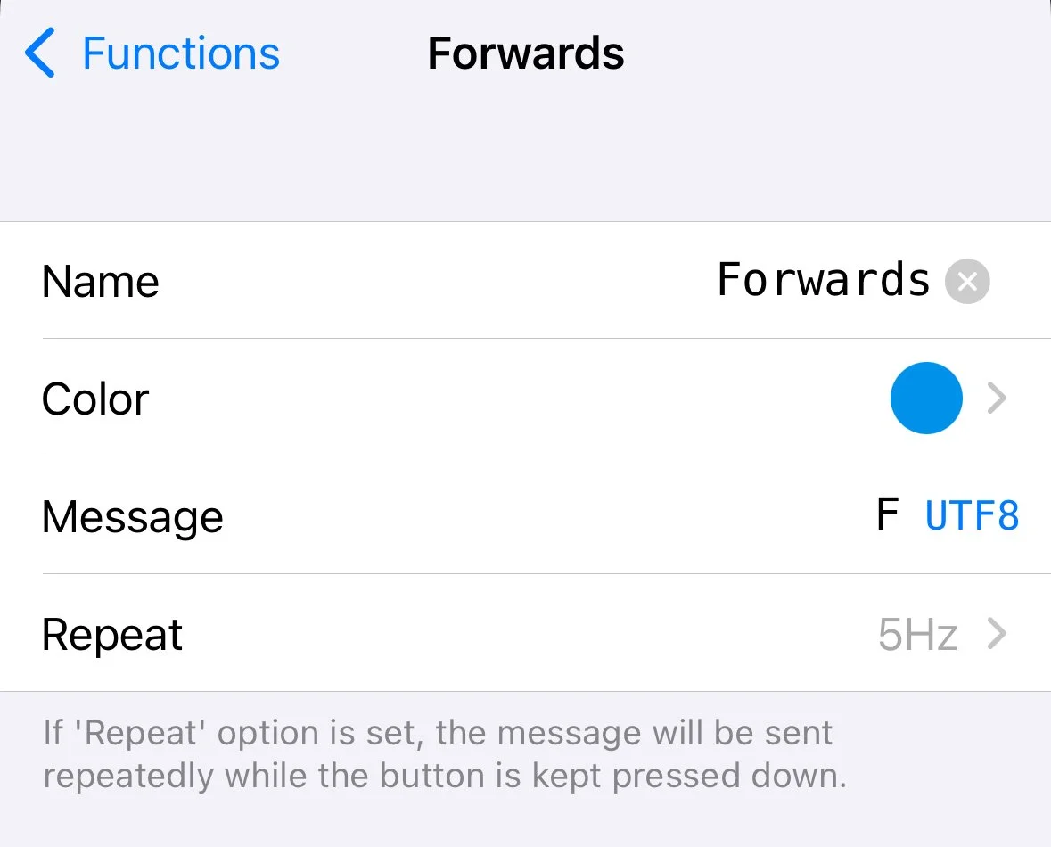
An example of the detailed settings inside each button
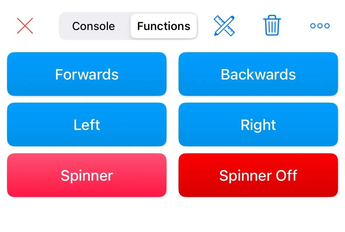
An example of the full button layout
7. Final Assembly
We’re into the final stretch! We’ve got the physical pieces, we have working electronics, and it’s finally time to put it all together. To begin, we need to collect up our pile of tools and parts: We need our screwdriver, our pliers, tiny zip ties, and command strips. We also need all of the flat parts of the robot, the body we glued together earlier, all of the electronics, and all of the bolts for the project (both the ones we purchased, and the ones that came included with the TT Motor Mounts). There is a full video at the bottom of this section of the assembly process.
First, we start with the easiest pieces. Grab the two rear support legs, four M4 x 10mm bolts, and four M4 nuts. You’ll also need your screwdriver, and the pliers to hold the nuts in place to tighten the bolts. These pieces install on the rear of the chassis, and press the body of HUGE against the ground, allowing it to drive around.

Next, find the two angry eyes, along with two M4 x 10mm bolts and two M4 nuts. In case you can’t tell where these go, install them in the holes in the center of the front of the chassis. Angle them however you like!

Find your four TT Motor Mounts next, along with their 16 associated short M3 bolts, and 16 of the M3-sized nuts. This hardware should all come included along with the motor mounts. Set aside the long M3 bolts for now (along with the remaining eight M3 nuts) as we will use these later to mount the motors themselves. Each motor mount has associated holes in four locations of the chassis, and the vertical portion of the mount should be oriented as close to the edges of the chassis as possible (i.e. closer to the wheels than the motor, and closer to the blade than the motor). Place four bolts through the floor of the chassis for each mount, and secure the mounts into place with the nuts. For ease of assembly, we recommend having the nuts external, accessible underneath the chassis.


Setting aside the chassis for a moment, we will now put together the wheel and weapon hubs, which need to be assembled before mounting to the chassis. First find the two wheels, four M4 x 10mm bolts, and four M4 nuts. Also grab two of the TT Motor Snap-On Hubs. On each hub, slide a wheel over the central cylinder, and align the bolt holes with the wheel’s bolt holes. Ensure that the hub is oriented so that the wheel is mounted on the opposite side of the portion that connects to the motor axle. Insert the bolts, tighten the nuts, and set these aside for now.

The weapon hub comes next: find the spinning blade, the three spinning blade spacers, and the two remaining TT Motor Snap-On Hubs. This hub will use the two M4 x 16mm bolts that we purchased, along with the last two M4 nuts. Assemble the weapon hub as shown below, with one spacer and the blade on one hub, and both remaining spacers on the other hub. Tighten the bolts, and set this aside with the assembled wheel hubs.


Back to the chassis! We’re ready now to put the motors in. If you haven’t already, you’ll need to disconnect the motor wires from the electronics that we assembled earlier. Be sure to note which wires belong to which connector, or consult the earlier wiring guide for re-wiring once everything is mounting inside the chassis. This is the point where we recommend using the small zip-ties also, to hold motor wires together and help easily organize the reassembly process. We’ll be starting with the motors for the weapon, as they are easier to tighten when the drive motors are not installed.
Be sure to find two of the long M3 bolts from earlier, as well as two of the M3 nuts. Slide these bolts through the motor, and install the motor on one of the mounts in the center of the chassis. We preferred to have the nuts in the center of the chassis, by the weapon blade, so that our screwdriver could reach the bolts through the frame hole where the wheel mounts. Be sure that the wires of the motor are oriented to point towards the open area in the frame, to facilitate wiring later. As you slide this first motor into place, take the weapon hub and slide it onto the motor shaft. Once the motors are installed, the weapon hub cannot be easily removed, so it must be installed along with the motors.
Next, repeat the weapon motor process with motor #2, and another set of the long M3 bolts (and nuts). As this motor is tightened into place, it should also mesh with the second TT Motor Snap-On hub. You may have to rotate the blade to ensure that the hub and axle align, and you may have to flex/loosen the motors slightly to get the blade attached.


We’re almost there! Grab the last two motors, and the remaining hardware (four long M3 bolts, and four M3 nuts). Install these motors in a familiar fashion, on the two unused motor adapters. For these, we prefer to have the head of the bolt facing outwards, with the nut installed inside the chassis. This felt like the easiest way to access the bolt head to properly tighten the motor into place.


Once both motors are installed (with wiring oriented towards the open internal space), the wheel hubs can be slid on. Congratulations, you now have a free-standing HUGE!

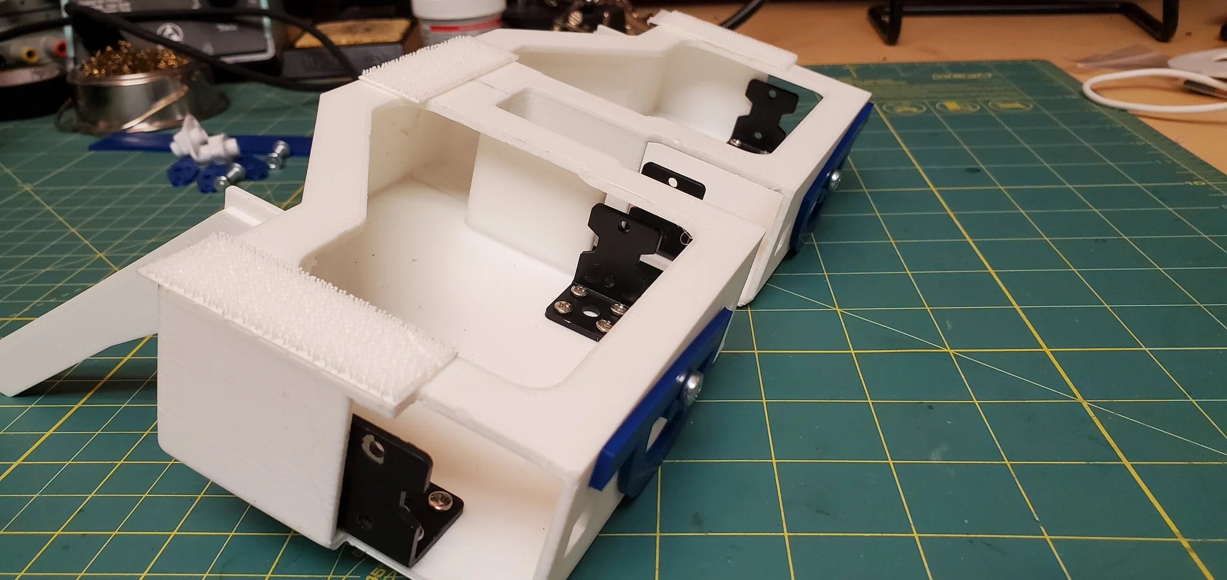
Finally, the electronic control boards can be placed into the chassis. Motor wires will need to be reattached, as well as the 4 wires which connect the drive and weapon motor controllers. Some of these will need to be threaded through the back of the chassis. Consult the earlier wiring instructions to make sure that this is done properly. We found it easiest to re-assemble the wiring with the boards sitting on top of the chassis, and then once-done, placing them inside. We also preferred to attach the controllers to the chassis with command strips, which keep them in place while allowing us to remove the boards whenever needed. Once this wiring is done, your HUGE should look like this:
We find that the batteries fit best in the rear portion of the chassis. It is important to once again ensure that your polarity is correct before installing the batteries!

Finally, we used three command strips to provide attachment points for the top plate(s). First, mount 3 command strips in the following location on the base chassis. If you 3d-printed the top plate in two pieces, cut a command strip in half for the rear of the top plates, they can both utilize the same command strip on the rear of the frame. Stick all of these into place on the top plates (hold roughly 30 seconds to ensure good adhesion) and your HUGE is mechanically complete!

They may be hard to see, but look behind the drive motor mounting holes, and at the back-center of the chassis.
At this point, another test should be done to ensure that all of the wiring was re-assembled correctly. As this HUGE has no on/off switch, the robot is “On” as soon as the batteries are plugged in. And conversely, the robot will only be turned “Off” once the batteries are removed (otherwise the batteries will die). We tucked both 9V batteries into the rear portion of the chassis (double checking polarity!). But once it is powered on, just connect the bluetooth and enjoy the robot you have built!
8. Fun!
You made it, and that’s amazing! Thanks for supporting Team HUGE and Mouser Electronics. Once done, please share videos/pictures of the build and tag @MouserElec, @BattlebotsHUGE, and use #RCHuge!
If you have any thoughts or feedback to share, please contact Team HUGE through any of our social media pages: Facebook, Instagram, or TikTok.
Appendix:
For those who would like to reference the Original code and instructions from Section 6, they are included here. We can’t promise that any of this is functional or useful.
To begin, download the Arduino software for interfacing with the Drive Motor Controller. At the time of writing, this was Arduino version 1.8.19.
https://www.arduino.cc/en/software
CAVEAT: This code is currently experiencing a bug. For the robot to operate properly, you must plug the motor controller into the computer, open the Arduino software, and open the Serial Monitor (these terms will be explained in a moment). Once that is done, and “Run Keyboard Control” appears, it can be disconnected and run as-described. This bug appeared just before release, and we are still tracing it. This post will be updated once it is resolved.
Then find the Micro USB Cable purchased earlier, and connect the Drive Motor Controller to a USB port on your computer. You will see a small light turn on on the drive motor controller, indicating that it has power. Try not to touch the board itself while it is powered on, or you may damage it! Our first steps will be to configure the Arduino software to interface with the board. Underneath the “Tools” dropdown, find the “Board” dropdown and select “Arduino Uno”. Then, also under the “Tools” dropdown, open the “Port” dropdown and select the board. In our case, the board was the only available connection, and was connected via “COM4”. Yours may have a number other than 4, but likely will still have “COM” in the title.
Next, open the code file (known as a “sketch”) from within the Arduino app. This is literally the brains of the operation! This code is developed-from a modified version of the test code available within the drive motor controller’s manufacturer documentation. It is simple code, and functions by submitting a letter via the serial monitor. Depending on the character submitted, a number of functions can take place. The weapon can be turned on, and the robot can drive forwards, backwards, and turn left and right (for a set duration of time). To ensure the code is written properly, click the check-mark in the top left corner to “Verify” the code. This will tell you if there are any bugs, and compile the code. After seeing “Done Compiling” appear in the bottom left corner, click the arrow that reads “Upload”. Once “Done Uploading” appears in the bottom left corner, you are ready to run!
First, we are going to test the electronics via the serial monitor. Open the serial monitor using the Magnifying Glass styled button in the top right corner of the Arduino software. “Run keyboard control” should print in this window, once you open it.
To allow the motors to actually turn, we now plug in one of our 9V batteries for the first time. It is extremely important that you plug the battery in, in the correct direction! Doing this step backwards can damage the control boards. The polarity is shown in the photo below, large plugs must interface with small plugs. If you would like to be extra safe, you can remove the 9V battery snap from the board (unplug it from the computer first) and connect it to the 9V battery elsewhere. Then reinstall into the motor controller.
Okay, we have wiring, power, and code. It’s time to test! With the board connected to the computer, and the Serial Monitor open, try any of the following commands.
“z” - Prints “Hello” into the Serial Terminal
“w” - Prints “Move Forward” and turns drive motors
“s” - Prints “Move Backwards” and turns drive motors
“a” - Prints “Turn Left” and turns drive motors
“d” - Prints “Turn Right” and turns drive motors
If that works, excellent! Now connect your second 9V battery to the weapon motor controller. Another light should come on there, once it is connected. Now try the following commands.
“q” - Prints “Spinner on” and turns weapon motors on
“e” - Prints “Spinner off” and turns weapon motors off
If this all works, congratulations! Let’s get it working wirelessly.
First, download this Arduino app from the Android app store:
https://play.google.com/store/apps/details?id=com.cloudland.blunoble&hl=en_US&gl=US
UPDATE: App no longer available, working on a solution
As noted above, we don’t own an Apple device to test this with. Our testing was functional with a Samsung Galaxy S10e, running Android version 12.
Under your cell phone’s normal bluetooth connections window, look for “Bluno” and select it. If it is named something else, you should be able to rename it to whatever you like within these settings. When prompted for a password, enter “000000”. This will pair the arduino with your phone. Exit out of this window and open the Arduino BLE app.
Once in the app, tap the “SCAN” button. Once it appears, tap “Bluno” to connect with it. If this works, you should see a blue light appear on your drive motor controller. If it does, that’s a great sign! We aren’t done yet though. Under the “CONTROLLER” tab within the app, click the gear icon and make sure that each button’s input matches the screenshot below.

App Settings
Within the Arduino BLE app, you will need to make sure that you’ve configured your controller properly. Utilize these settings, to match the code.
Click save, head back to the “CONTROLLER” tab, and your robot should be functional! Tap buttons quickly to run the drive motors, and turn the weapon motors on and off!